Introduction to operational amplifiers

Practical op amp model

Practical operation amplifier model.

Key-part_1

Key-part_2


In an ideal operational amplifier (op amp), the value of rd is considered to be infinite when in actual fact the resistance is around 10MΩ. This value is dependent on the variety of omp amp and generally increases with price. The higher the value of rd, the better.

This same premise also applies to the open-loop gain. It’s value in an ideal op amp is also considered to be infinite, when in actual fact it is around 10M.

ro however is the inverse, as in an ideal op amp it is 0Ω and a typical practical value is about 10Ω,


Vout_formula

Using the above formula the following can be derived:

V difference formula

The difference between the voltage on the inverting input and the non-inverting input is equal to the output voltage divided by the gain.

Now assuming ideal values for the gain (infinite), its value can substituted in and the formula can be rearranged.

V difference formula (values)

Any value divided by infinity is equal to zero, therefore:

V difference formula (simp)

Looking back at the original formula, the following can be deduced:

Vout_formula (2)

Vout_formula (3)

Substitute in the value for Vd:

Vout_formula (4)

Rearrange:

Vout_formula (5)


In addition to this, two more values can be stated when using ideal values.

The value of rd is infinite, therefore no current is flowing into the inverting or non-inverting terminals (Ip = 0A and In = 0A).

The output impedance is 0Ω.


What is slew rate?

The slew rate is the maximum rate at which the output voltage can change. This is especially relevant when amplifying sound waves using an op amp.

slew rate is the maximum change in voltage that can be achieved per second. The unit typically used is V/μs.

For example, a slew rate of 0.5 V/μs would be calculated using this formula:

2 x π x f x V = Slew rate (V/s)

So in this case you’d first convert 0.5 V/μs to 500 000 V/s.

Then to find the maximum voltage for a 1KHz signal you’d use this formula:

500 000/ (2 x π x 1000) = 15.71 volts.

This also means that a 1KHz signal can have an amplitude of 15.71 volts.

To put this into context, the human range of hearing is 20Hz to 20KHz. Therefore when amplifying audible sound you could have an amplitude of up to 3.98volts with this slew rate. Meaning that this op amp would be suitable for a 20KHz signal with an amplitude of 3.98 volts or less.

However when amplifying a 40KHz signal (a typical ultrasonic frequency), you’d only be able to achieve an amplitude of 1.989 volts. meaning that this op amp would only be suitable for 40KHz frequencies with an amplitude below 1.989 volts.


Comparators

A comparator is one of the simplest op amp subsystems. It simply compares two voltages, and the output either goes high or low depending on which input is the higher voltage.

Generally, one of the inputs is fixed to a set voltage (a reference voltage), whilst the other varies depending on an analogue input. Here’s an example:

Comparator

Using a potential divider calculation, the voltage at the non-inverting input can be calculated as 3v. Because of this, when the voltage at Vin is above 3v, the output will be low. When the Voltage at Vin drops below 3v, the output will be high.

Schmitt Triggers

A Schmitt trigger has one input and one output. It sets the output to one of two states depending on the voltage at Vin. Because of the nature of inverting op amp set-ups, the outputted signal will be inverted. When Vin goes below a certain voltage (the lower switching threshold), Vout goes high. When Vin goes above a certain voltage (the higher switching threshold), Vout goes low.

Schmitt Trigger

Because Schmitt triggers have an upper and lower switching threshold, they’re much better at cleaning up noisy signals than a single switching threshold. This is because with a single threshold, the noisy signal will jitter between each side of the threshold, causing it to  trigger multiple times.

Non-Inverting Amplifier

A Non-inverting amplifier increases the amplitude of a signal. Its input resistance is that of the op amp itself (infinite in an ideal op amp), which makes it perfect for amplifying small signals, that can provide very little current on their own.

One thing to note quickly. The output can never be higher than the positive supply voltage, or lower than the negative supply voltage.

Non-inverting amplifier

Non-inverting amplifiers however, can only provide a minimum gain of one. This means the output will always be at least the same value as the voltage on Vin. Its gain can be calculated by using the following formula:
Gain=1+RfR1

Inverting Amplifier

An inverting amplifier increases the amplitude of a signal. But due to the fact that the signal is fed into the inverting input, the output signal will be inverted. However, unlike Non-inverting amplifiers, they can have a gain of less than one.

One thing to note quickly. The output can never be higher than the positive supply voltage, or lower than the negative supply voltage. This means that for an inverting amplifier to work you need the negative supply pin to have a voltage below ground (e.g -6v).

Inverting amplifier

In inverting amplifiers, the gain can be calculated by dividing Vout by Vin. In addition to this, the same figure can also be acquired by dividing the feedback resistance by the input resistance ( feedback resistance = Rf, Input resistance = R1) . However, because the output is inverted, the value of the feedback resistance needs to be inverted too. From all of this, we can deduce the following equations:

Gain=VoutVinGain=-RfR1

If two inverting amplifiers are used in series, the inversion can be rectified. A schematic and equation is shown below to demonstrate this.

Inverting amplifiers in series

The gain of the first op amp is calculated:

IA1


Then the gain of the second op amp:

IA2

Now assuming that Vin = 0.5v, the output of the first op amp would be the following:
IA3

Finally, with -5v being inputted into the second op amp, the output will be once again positive:

IA4

Therefore the total gain of the circuit is 10, meaning that the inversion has been rectified.

Operational Amplifiers

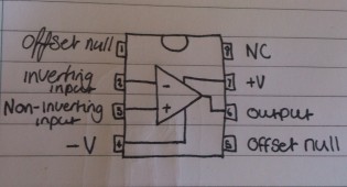
Op Amps (Operational Amplifiers) are composed of two inputs, an output, and positive and negative power supply pins.

Op Amps can be used in many different set-ups, among them being: Voltage Comparators, Inverting and Non-inverting amplifiers, Summing amplifiers, and Difference amplifiers.

In Op Amps, the voltage of the output is dependent on the voltages of the two inputs. If the Inverting input is higher, the output will be the same as the negative supply. If the Non-Inverting input is higher, the output will be the same as the positive supply.

Pins 2, 3, 4, 6, and 7 are the only pins which need to be connected to the circuit in order to use the Op Amp.

LM741 Operational Amplifier actual viewop amp schematic